


Reciprocating compressors are the dominant compression technology in biomethane production, and for good reason. Their ability to deliver high compression ratios, handle variable gas compositions, and operate efficiently across a wide range of pressures – from near-atmospheric suction to 250 bar and above – makes them uniquely suited to the demands of biogas upgrading, grid injection, liquefaction, and high-pressure storage applications.
At Fornovo Gas, reciprocating compressor technology is our core expertise. Our entire product range – the DA500, DA300 and SA200 compressor – is built on reciprocating architecture, refined through more than 55 years of engineering experience and over 3,000 compressors installed worldwide across more than 60 countries. This guide is written for project engineers specifying compression equipment for biomethane projects, providing the technical depth needed to make informed decisions about compressor selection, staging, pressure range, materials, and sizing.
How reciprocating compressors work
A reciprocating compressor is a positive displacement machine that uses a piston moving within a cylinder to compress gas. The operating cycle is fundamentally simple, which is precisely why this technology has proven so reliable and long-lived in industrial gas compression.
The compression cycle step by step
Each piston stroke completes a four-phase thermodynamic cycle:
- Expansion – the piston begins its return stroke. Gas trapped in the clearance volume (the small space between the piston and the cylinder head at top dead centre) expands as the piston moves away from the head.
- Suction (intake) – as the expanding gas drops below suction pressure, the suction valve opens and fresh gas flows into the cylinder. The piston continues its stroke, drawing gas in at suction conditions.
- Compression – the piston reverses direction and begins compressing the gas. Both suction and discharge valves are closed. The gas volume decreases and its pressure rises progressively.
- Discharge – when the gas pressure exceeds the discharge pressure plus the valve spring resistance, the discharge valve opens and compressed gas is pushed out of the cylinder into the downstream piping.
This cycle repeats with every crankshaft revolution – or twice per revolution in a double-acting cylinder, where gas is compressed on both sides of the piston simultaneously. Depending on the compressor configuration and application requirements, Fornovo Gas reciprocating compressors are designed to operate at the most suitable rotational speed to ensure reliability, efficiency and long service life.
Key mechanical components
Understanding the main components helps project engineers evaluate compressor specifications and maintenance requirements:
- Crankshaft and crankcase – the crankshaft converts rotational motion from the motor into the linear reciprocating motion of the piston. The crankcase houses the crankshaft, bearings, and lubricating oil system. In an oil-free compressor, the crankcase is still lubricated – only the gas-contact side of the cylinder is oil-free.
- Connecting rod and crosshead – these link the crankshaft to the piston. The crosshead constrains the piston rod to linear motion, preventing lateral loads on the cylinder and packing – a design feature that is particularly important for long-stroke, high-pressure biogas applications.
- Cylinder and piston – the cylinder is the pressure vessel where compression occurs. Piston design, ring material, and bore finish are critical to sealing efficiency and service life. Fornovo Gas offers a wide range of cylinder-piston modules with three stroke options (80 mm, and 110 mm on the DA500 platform) to match different capacity and pressure requirements.
- Valves – suction and discharge valves are automatic, pressure-actuated components. Valve design directly affects volumetric efficiency, power consumption, and reliability. Poor valve performance is one of the most common causes of compressor underperformance in the field.
- Piston rings and rod packing – piston rings seal the gap between piston and cylinder wall. Rod packing seals the piston rod where it exits the cylinder. In oil-free designs, these use PTFE-based or carbon-filled polymer compounds instead of metallic rings running in an oil film.
Why reciprocating technology suits biomethane applications
Biomethane production imposes specific demands that favour reciprocating compressors over rotary or centrifugal alternatives:
In addition to biomethane applications, the same reciprocating technology is widely used for biogas upgrading, CNG, Bio-LNG, technical gases, CO2 recovery and hydrogen applications.
- High compression ratios – grid injection typically requires 24–75 bar, but storage and CNG applications demand up to 250 bar. Reciprocating compressors achieve these ratios efficiently through multi-stage compression, which is difficult or impossible with single-stage rotary machines.
- Flow rate flexibility – reciprocating compressors maintain efficiency across a wide turndown range. Biogas plants often experience variable gas production rates depending on feedstock availability and digester conditions. Capacity can be adjusted through speed variation, valve unloading, or clearance pocket adjustments without significant efficiency penalties.
- Tolerance for variable gas composition – biogas composition fluctuates with feedstock type and digestion conditions. Reciprocating compressors handle these variations without the surge risks that affect centrifugal machines.
- Oil-free capability – reciprocating technology can be engineered for completely oil-free gas contact, which is essential for biomethane applications where gas purity standards prohibit oil contamination. This is a capability that most rotary screw and centrifugal compressors cannot match at the same pressure levels.
Single vs multi-stage compression: choosing the right configuration
One of the most important engineering decisions in biomethane compressor specification is the number of compression stages. This choice directly affects energy efficiency, discharge temperature, equipment cost, and physical footprint.
What determines the number of stages?
The number of stages is driven primarily by the overall compression ratio – the ratio of discharge pressure to suction pressure. As a general engineering principle, each compression stage is designed according to the application requirements, gas composition, discharge temperature limitations and overall compression ratio. The optimal stage ratio is determined during the engineering phase.
Higher per-stage ratios are technically possible but result in elevated discharge temperatures, increased thermal stress on components, reduced volumetric efficiency, and greater power consumption. Multi-stage compression with intercooling between stages resolves all of these issues simultaneously.
Biomethane application staging examples
The number of compression stages is determined during the sizing process and depends on suction pressure, discharge pressure, gas composition, operating temperatures and customer requirements. While multi-stage compression is common in many biomethane applications, the final configuration is always defined on a project-specific basis. The examples below must therefore be considered indicative only.
| Application | Typical suction pressure | Typical discharge pressure | Typical stages |
| Upgrading system feed | Near atmospheric (1 bar a) | 9-16 bar g | 2 stages |
| Grid injection | Near atmospheric or post-upgrading (8-14 bar a) | 70-75 bar g (varies by network) | 2–3 stages |
| High-pressure storage / CNG | Post-upgrading (typically 8-14 bar g) | 200–250 bar g | 3–4 stages |
The role of intercooling
Between each compression stage, the gas passes through an intercooler – a heat exchanger that reduces the gas temperature back toward ambient conditions before it enters the next stage. Intercooling serves several critical functions:
- Reduces power consumption – compressing cooler gas requires less energy, because the gas is denser and closer to the theoretical isothermal compression path.
- Protects components – lower discharge temperatures extend the life of valves, piston rings, packing, and cylinder components. This is especially important for oil-free compressors where dry-running ring materials have temperature limits.
- Removes condensate – cooling the compressed gas causes moisture and heavier hydrocarbons to condense out, protecting downstream stages and equipment. In biogas compression, this also helps manage the moisture that is inherently present in saturated biogas.
Fornovo Gas compressor packages include integrated intercooling systems – either water-cooled or air-cooled depending on the project requirements and site conditions. The cooling system design is part of the custom engineering process for every project.
Single-stage vs multi-stage: decision criteria
| Factor | Single-stage | Multi-stage |
| Capital cost | Lower | Higher (more cylinders, intercoolers, piping) |
| Energy efficiency | Lower for high ratios (high discharge temperature wastes energy) | Higher (intercooling reduces cumulative power consumption by 15–25%) |
| Discharge temperature | High – can exceed material limits for ratios above 4:1 | Controlled – each stage operates within optimal temperature range |
| Component life | Shorter at high ratios due to thermal and mechanical stress | Longer – each stage operates under moderate conditions |
| Physical footprint | Smaller | Larger (additional stages and intercoolers) |
| Suitability for biomethane | Limited to low-ratio boosting applications only | Required for grid injection, storage, LNG, and CNG applications |
For many biomethane applications, multi-stage compression is selected when required by the pressure ratio, temperature limits and process conditions. Fornovo Gas compressor families can be configured with different cylinder arrangements according to project requirements, allowing the number of stages to be defined during the sizing process.
Pressure range selection for biomethane applications
Specifying the correct suction and discharge pressures is the starting point of any compressor sizing exercise. The pressure range is determined by the application, and each biomethane end use has its own requirements:
Grid injection
The required injection pressure depends on the gas network. Grid injection pressure requirements vary according to the country, gas network operator and connection point, from low-pressure distribution networks to higher-pressure transmission systems. The compressor must deliver biomethane at or above the network’s minimum injection pressure, accounting for pressure losses through the interconnection pipework, metering, and odorization equipment. Fornovo Gas routinely engineers compressors for grid injection across the full spectrum of European network pressures.
Biomethane liquefaction (bio-LNG)
Feed gas pressure requirements depend on the liquefaction technology adopted and the process configuration selected by the plant designer. Some processes use higher-pressure feed gas to improve liquefaction efficiency. The compressor specification must be coordinated with the liquefaction system supplier to ensure compatible pressure and temperature conditions at the interface.
High-pressure storage and trailer filling
Biomethane storage at up to 250 bar g in cylinder banks or tube trailers requires multi-stage compression from upgrading outlet pressure (typically 8-14 bar g) to the target storage pressure. This is the highest-pressure application in the biomethane value chain, and the compressor design – including number of stages, intercooling capacity, and high-pressure cylinder metallurgy – must be precisely engineered for reliable continuous operation at these pressures. Fornovo Gas compressors are designed for storage applications up to 350 bar.
CNG refuelling stations
CNG stations typically compress gas to 200–250 bar g for vehicle fuelling. The suction conditions depend on whether the station receives gas from a pipeline (at network pressure) or directly from an on-site biomethane plant. Buffer storage design interacts with compressor sizing to determine the optimal cascade pressure strategy.
Material considerations for biogas compression
Biogas is not a benign gas. Its composition presents specific material challenges that must be addressed during the compressor engineering phase. Selecting the wrong materials for gas-wetted components can lead to premature failure, unplanned shutdowns, and costly repairs.
Moisture and condensate management
Biogas leaving the digester is typically saturated with water vapour. During compression, this moisture condenses in intercoolers and low points of the piping system. Material selections must account for wet-gas conditions throughout the compression train. Cylinder liners, valve components, and internal fasteners must resist both aqueous corrosion and the combined attack of water and H₂S. Fornovo Gas selects compressor configuration and materials according to the gas analysis, operating conditions and project requirements.
Siloxane deposits
Siloxanes – silicon-based organic compounds present particularly in landfill gas and wastewater treatment biogas – decompose during compression to form hard silicon dioxide (SiO₂) deposits on hot surfaces. These abrasive deposits can score cylinder bores, damage valve seats, and accelerate ring wear. Material hardness, surface treatments, and operating temperature management are all part of the mitigation strategy. In severe siloxane environments, more frequent ring and valve inspection intervals may be necessary, and the compressor operating parameters may be adjusted to minimise deposit formation.
Material summary by component
| Component | Standard gas service | Biogas-specific considerations |
| Cylinder liner | Alloyed steel | Corrosion-resistant alloys or coatings for wet H₂S environments; hardened finishes for siloxane-prone gases |
| Piston rings | Metallic or polymer (oil-free: PTFE-based) | Compound selection matched to gas composition – H₂S-resistant, moisture-tolerant formulations |
| Valve plates | Stainless steel or thermoplastic | Upgraded metallurgy for acid gas service; thermoplastic options for improved chemical resistance |
| Piston rod | Nitrided steel | Corrosion-resistant plating or overlay for wet sour gas conditions |
| Springs and fasteners | Standard alloy steel | Alloyed steel
|
| Gaskets and seals | Standard elastomers | Chemical-resistant elastomers selected for specific gas composition |
At Fornovo Gas, material selection is part of our custom engineering process. Our team evaluates the complete gas analysis – not just methane and CO₂ percentages, but the full spectrum of trace components including H₂S, moisture dew point, siloxanes, ammonia, and volatile organic compounds – before specifying any gas-wetted material.
Compressor sizing guidelines for biomethane projects
Correct compressor sizing ensures that the equipment can deliver the required flow rate at the specified pressures, without being excessively oversized (which wastes capital and energy) or undersized (which limits plant throughput). The key inputs to the sizing process are:
Required data for compressor sizing
- Gas composition – a full gas analysis is essential, not just methane percentage. The molecular weight, compressibility factor, and specific heat ratio all influence the thermodynamic calculations.
- Suction pressure and temperature – the conditions at which gas enters the compressor. For raw biogas compression, suction is typically near atmospheric. For post-upgrading compression, suction pressure depends on the upgrading system’s outlet pressure.
- Discharge pressure – determined by the application (grid injection pressure, storage pressure, LNG feed pressure, etc.).
- Required flow rate – specified in Sm³/h (standard cubic metres per hour) or Nm³/h (normal cubic metres per hour). The reference conditions (temperature and pressure) for ‘standard’ and ‘normal’ volumes vary by country and must be clearly defined.
- Inlet gas temperature – affects gas density at suction and therefore the actual volumetric flow the compressor must handle.
- Ambient conditions – altitude, ambient temperature range, and cooling medium availability (water temperature or ambient air temperature) affect intercooler performance and overall compressor efficiency.
- Operating profile – continuous duty, intermittent, or variable load? Most biogas and biomethane plants are designed for continuous operation, although actual operating profiles may vary depending on plant configuration and maintenance strategies.
Sizing process overview
The compressor sizing process follows a structured engineering workflow:
- Step 1: determine thermodynamic properties – using the gas composition, calculate the compressibility factor (Z), specific heat ratio (k), and molecular weight at suction and discharge conditions for each proposed stage.
- Step 2: define staging – divide the overall compression ratio into stages with per-stage ratios of approximately 2.5:1 to 4:1, ensuring discharge temperatures remain within acceptable limits after each stage.
- Step 3: calculate cylinder swept volume – for each stage, determine the swept volume required to deliver the target mass flow, accounting for volumetric efficiency losses due to clearance volume, valve losses, gas heating, and leakage.
- Step 4: select cylinder-piston module – match the required swept volume to available cylinder bore and stroke combinations. The DA500 platform offers three stroke options (80, 110 mm) and a wide range of bore diameters, providing extensive flexibility in this step.
- Step 5: calculate power – determine the indicated power for each stage and sum to find the total compressor power requirement. Add mechanical losses (friction, auxiliaries) to arrive at the shaft power, which determines the motor size.
- Step 6: verify thermal performance – check discharge temperatures, intercooler duties, and aftercooler performance against material limits and process requirements.
- Step 7: validate dynamic performance – assess pulsation, vibration, and torsional behaviour. Fornovo Gas uses virtual prototyping and FEM analysis during the design phase to simulate realistic workloads and optimise dynamic balance.
Common sizing mistakes to avoid
- Using ideal gas assumptions for high-pressure stages – at pressures above ~20 bar, real gas effects (compressibility) become significant. Using ideal gas equations leads to undersized cylinders and insufficient motor power.
- Ignoring altitude effects – sites at higher elevations have lower atmospheric pressure and air density, which affects both suction conditions and air-cooled intercooler performance.
- Specifying flow rate without clear reference conditions – ‘standard’ conditions vary by region (0°C vs 15°C vs 20°C; 1 atm vs 1.01325 bar). A 5% flow rate error can result from mismatched reference conditions between the plant design and the compressor specification.
- Overlooking future capacity requirements – if the biogas plant is expected to increase capacity (additional digesters, new feedstock sources), specifying a compressor with some turndown and turn-up capability avoids costly early replacement.
Horizontal vs vertical compressor configurations
Reciprocating compressors for biomethane are available in horizontal and vertical configurations, each with distinct advantages:
| Factor | Horizontal (e.g. DA500) | Vertical (e.g. DA300, SA200) |
| Power range | Available in a wide range of power ratings depending on compressor configuration and application requirements | Small to medium range |
| Cylinder capacity | Different cylinder arrangements according to project requirements (Up to 6) | Typically 2-3 cylinders |
| Footprint | Wider | Smaller floor area |
| Vibration characteristics | Optimised balancing for minimal vibrations | Inherently balanced vertical forces; lighter foundation requirements |
| Maintenance access | Excellent – horizontal cylinders at working height | Good – vertical cylinders may require overhead access |
| Typical applications | Large upgrading plants, grid injection, high-pressure storage, LNG feed | Medium-capacity plants, farm-scale biogas, space-constrained sites |
| Speed range | Defined according to compressor configuration and application requirements | Variable by model |
The choice between horizontal and vertical configuration depends on the project’s capacity requirements, physical space constraints, and integration with the plant layout. Fornovo Gas offers both configurations within the same oil-free, non-lubricated, and hydrogen-ready technology platforms, ensuring that the compressor format matches the project without compromising on technology.
Compressor packaging: from bare shaft to turnkey system
Fornovo Gas delivers compressors in three packaging levels, depending on the project’s integration requirements:
- Bare shaft compressor – the compressor frame, cylinders, and valves, ready to be integrated into the customer’s own skid or plant design. All bare shaft units undergo a no-load test to verify correct mechanical operation before shipment.
- Skid-mounted package – the compressor, motor, intercoolers, piping, instrumentation, and control panel assembled on a structural steel skid. Factory testing procedures are defined according to the project scope and applicable technical requirements.
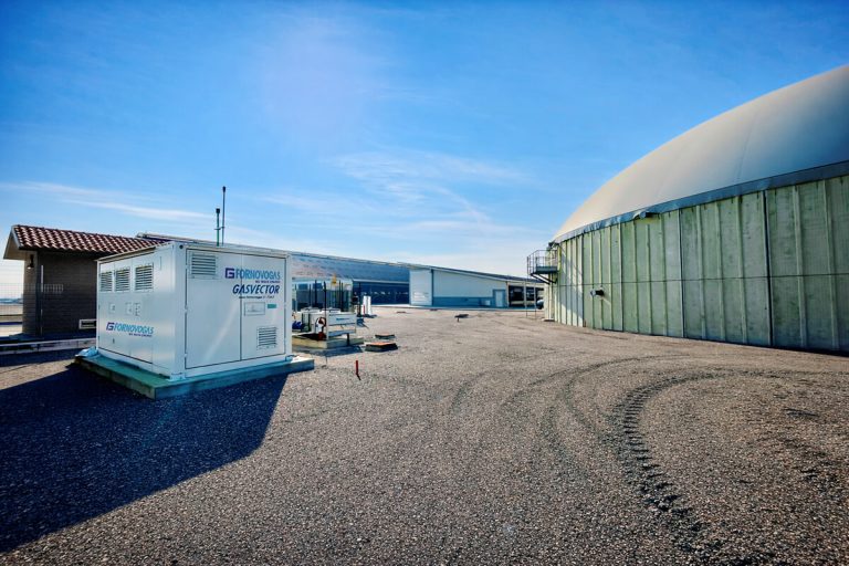
- Gasvector cabinet system – a fully enclosed, pre-engineered solution with integrated soundproofing (designed according to project-specific noise requirements), HVAC, and safety systems. The Gasvector provides a turnkey installation that minimises on-site engineering and is ideal for sites with strict noise requirements or limited construction resources.
This tiered packaging approach allows project engineers to choose the integration level that best fits their project timeline, on-site capabilities, and budget. The factory testing protocol – defined according to the project scope and applicable technical requirements – is a distinctive element of Fornovo Gas’s quality assurance process that provides documented evidence of compliance before the equipment leaves our manufacturing facility in Traversetolo (Parma).
Certifications and compliance standards
Biomethane compressors must comply with multiple European directives and international standards simultaneously. Fornovo Gas compressors carry the following certifications:
- ATEX Directive 2014/34/EU – for installation in explosive atmosphere zones (Zones 1 and 2). Essential for all biogas applications where flammable gas is present.
- PED Directive 2014/68/EU – Pressure Equipment Directive, with G-module certification for each individual machine.
- Machinery Directive 2006/42/EC – covering mechanical safety requirements.
- EMC Directive 2014/30/EU – electromagnetic compatibility compliance for control systems and instrumentation.
- ISO 9001 – quality management system certification, ensuring consistent manufacturing processes.
- ISO 14001 – environmental management system certification.
- ISO 45001 – occupational health and safety management system certification.
- EAC certifications – for Eurasian Economic Union markets (Russia, Belarus, Kazakhstan, Kyrgyzstan, Armenia).
- Achilles validation – registered and validated with Achilles, as part of its supplier qualification process.
For projects outside Europe, Fornovo Gas also supports SONCAP (Nigeria) and PVoC (Tanzania) certifications, and can work with customers to meet additional country-specific requirements.
